Project Summary
We are designing a system for use with existing tennis ball launchers. Our system will retrieve balls hit over the net and automatically feed them back to the ball machine. This will allow the athlete to play many times longer without needing to stop and collect the balls.
Intro
Our system will work in conjunction with existing tennis ball machines used for practice. A variety of ball machines are available, many of which can vary the speed, direction and type of shot. Two examples are shown in the Background section below.
Ball machines typically hold a large number of balls, and the user must stop and collect all of the balls when they run out. Our project aims to solve this problem by automatically feeding the balls back into the ball machine. This will allow the athlete to play many times longer without needing to collect the balls. Alternatively, the user would be able to purchase significantly fewer tennis balls (which go flat and must be replaced).
Most commercially available ball machines cost at least $650-$700, and often cost $1000-$2000 or more. We want to design a system that will significantly improve the usefullness of these machines for a relatively minor additional cost.
If our system can return a fraction r of balls hit, play time should theoretically be extended by the following gain factor:

An 80% return rate would correspond to a gain factor of 5, while a 95% rate would extend play by a factor of 20. In reality, we expect the actual gain factor will be slightly less since it will not be worthwhile to continue hitting when a very small number of balls remain in the system.
Background
Examples of existing tennis ball machines:
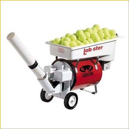
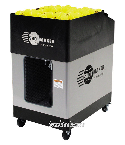
Several relevant patents are listed in the Intellectual Property section below.
Intellectual Property
Other methods for collecting tennis balls:
US 4116436: Ball-Collecting Apparatus
US 4938479: Tennis Ball Return Apparatus (collects balls that hit the net)
US 4456252:Tennis service practice court with recovering and collecting means
(separate type of court with only the service area on one side)
US 4004806: Apparatus for Collecting Balls
(lip around the edge, and some other devices)
US 3989245: Tennis Practice Device Having Pneumatic Ball Projector (separate court that is sloped)
US 4112911: Ball Collector and Projector Apparatus (uses conveyer belts)
US 4108432: Tennis Ball collection, pick up, and propelling system
Proposed Solutions
Possible solutions:
- system of nets that funnel into a simple conveyor belt
- sweeping over the court
- navigating the perimeter of the court
- blowers
Evaluation and optimization criteria:
- percentage of balls returned (of those hit over the net)
- setup and breakdown time
- system cost
- collapsibility and size
- energy demand
Here are some of our notes:
notes_1
notes_2
Once tennis balls are captured within the system, there are various ways we could convey them to the desired location:
Method
|
Pros |
Cons |
| Standard conveyor belt |
this is straightforward and would work |
expensive, mechanically complex, bulky |
| Simple conveyor using rope or chain |
cheaper and simpler than a full conveyor belt |
uncertainties in design |
| Smooth ramp |
simple, cheap, no power required |
requires a significant height to convey balls a large distance |
Experiment 1
10/4/2009
In order to better understand our problem, we went out to a tennis court and hit a lot of shots to observe where and how the balls would land. Here are some of our pictures and observations:


Observations:
- balls hit over the net overwhelmingly end up at the perimeter of the court, primarily at the rear
- netting over the chain link fence significantly damps balls bouncing off the fence
Experiment 2
10/18/2009
We tested the critical angles at which a tennis ball will roll down an inclined plane surface. We tested wood and acrylic ramps, both in the static case (ball initially at rest) and kinetic case (ball nudged or dropped from a small height).
| Surface material |
Length |
Critical height (static) |
Critical slope (static) |
Critical height (kinetic) |
Critical slope (kinetic) |
| Wood |
24" |
1.40625" |
0.0586 |
1.0" |
0.0417 |
| Acrylic |
12" |
0.6825" |
0.0573 |
0.25" |
0.0192 |
First Prototype
Brainstorms
We have identified two steps to collecting the balls:
- Catching and localizing the balls within the system
- Moving the balls to the desired location
We would like our first prototype to test a simple design for this first step, catching and localizing a ball hit against the back fence. Also, we don't want it to interfere with the playing area of the court so players can see where the ball bounces and how it comes off the court.
One potential design for the prototype would look like this (side view):
Sketch of TBCS Prototype 10-7.pdf
There are a few manufacturers of tennis windscreens, a potential material in the design. Here are a couple sites I looked at.
http://www.mputterman.com/tennis-windscreens.htm?gclid=CJ_i6c6grJ0CFYZM5QodOnHIjQ
http://www.allcourtfabrics.com/
Results


Our first prototype tested some of the basic components of our collection system. We used a shower curtain to test how well a tarp offset from the fence would collect balls, and it did help significantly. An adjustable wooden ramp was used to determine the appropriate ramp slope to accept balls rolling towards the fence (not shown in video).
Some balls still bounced back beyond the boundary of the ramp, and a better tarp setup is needed. This was a very rough prototype: the tarp and ramp are not well secured, as seen in the video.
Second Prototype
Brainstorms
For the second prototype we would like to test a conveyance apparatus, potentially using knotted rope. We will use the basic design of the first prototype, but make it more secure, possibly connecting the ramp to the fence in some way.
Design plans:
- tarp will use LDPE sheeting to test whether this material will work (it is sufficiently inexpensive to use for the entire court)
- ramp will be secured to the ground and made of an inexpensive material, possibly cardboard
- knotted rope will be used for conveyance, and we also plan to test how much dragging friction it causes in order to determine what motor we should purchase
Schematic of rope conveyance:
rope_diagram2.pdf
Sketches for second prototype design
Materials:
-
At Home Depot we bought 1/4" diameter clothesline for the conveyer rope because it was rough enough to catch a tennis ball (when knotted) yet smooth enough not to cause a lot of friction when it drags along the ground.
-
For the tarp material we are going to compare LDPE sheeting and charcoal fiberglass window screen.
Here is part of our second prototype. The ramp includes extensions to attach to the fence, and the knotted rope for conveyance is shown. Surfaces with moving parts are made smooth with clear packing tape. The tarp or netting will attach to the track behind the ramp.

Motors
We are exploring various motor options. Here is one motor we are considering and have available:
Anaheim Automation High-Torque Gearmotor
- The motors available in Professor Daniels' lab are 17YPG306s-LW4-R14
Here is a partial CAD rendering of the drive wheels for the conveyance system. The wheels have flanges to guide the ropes, and one of them will be powered by the motor. The rope will criss-cross (sketches coming soon) so the wheels turn in opposite directions.

Here are some additional design scketches, including the motor drive attachment and the lift:
Further design sketches
Here are some of the parts we are using to construct the conveyor drive. This includes the motor, flexibile coupling, shaft, wheel material, and tread.

Results
We did some basic testing (11/29/09) using the mesh and LDPE plastic, two of the materials we are considering for the curtain. Both showed promise in different ways. The mesh is probably a better (and better looking) material, although the balls do bounce off of it if the mesh hangs too tightly. The plastic is not as nice of a material, although the loose, crumpled plastic was good at damping the incoming or falling balls. Balls still tended to bounce out of the system, and we are considering how to improve ball retention. Possibilities include weighting the curtain, hanging the curtain further from the fence, and adding better containment at the base of the system.
Final Construction
Three major components:
- Rope conveyor
- Conveyor drive
- Lift
Here is a recent photo of the final drive system during constriction:

We have decided to use DC gear motors to power the drive and lift. These should be easier to control than the stepper motors we had originally planned to use. We chose 12VDC gear motors from Jameco that run at 44 RPM when unloaded.
These photos show the lift drive, which attaches to the same central platform as the conveyor drive. The position of the drive can be adjusted in the vertical and front-back directions. This makes it easier to align and tension the lift.


For portability, the system runs on a 12V car battery (courtesy of Ben Howard). Attachment is by alligator clips. We also use a 12VDC adapter for running off wall current.

Here are the complete mechanics of the system, showing the conveyor drive and lift drive.

The ramp, rope conveyor, and attachment for the netting. The netting attaches behind an acrylic piece that folds over to create a smooth attachment.

Final Results
The complete system! The final prototype spans 12 feet of court. A final system would need to cover the full rear perimeter of the court, but this is primarily a matter of scaling.
The hanging mesh attaches to the fence with wooden supports. The supports hook onto the chain link at the top, and hold the mesh 20 inches from the fence.

Video of our final test:
A close-up of the final mechanics when fully assembled.

Conveyor and track.

Several balls in conveyance...

This view shows the back of the system, including the braces that attach to the fence and hold the track and conveyor at the proper distance.


Success!
Meeting our objectives:
We set out to design and build a system that would return a high percentage of balls hit over the net in order to significantly extend play when using a ball launcher (or simply allow for easier ball collection). We also wanted a system that could be easily set up on a standard tennis court without any modifications, and that would be constructed of inexpensive materials and require minimal energy usage.
We have successfully developed a final prototype that, if scaled to its full size, we believe meets our design criteria. Balls that are hit over the net and into the catch of the system are reliably conveyed to the central mechanics and lifted up to the desired height. Our system can be used on a standard tennis court, and is designed to attach to the standard chain link fence. Setup is simple: lay out the track, hang the mesh, position the central mechanics, and plug it in! We have chosen inexpensive materials, especially for the track and catch portions that would need to be scaled up in order to cover the entire rear perimeter of the court. The conveyor and lift run on a single 12V battery, and the conveyor has been streamlined to reduce the power required (smooth surfaces and minimalist design).
Considerations for future design:
- a full-scale system, covering the back of the court and the rear portion of the sides
- reducing the size of the central mechanics, and enclosing the moving parts where possible
- improved collabsibility (for ease of storage and setup/breakdown)
- a snazzy paint job that would blend in with the aesthetic of a tennis court
Tennis Ball Collection System: more tennis, less fetching
Acknowledgements:
Jerry Daniels and Kipp Bradford - - our fine professors
Ben Howard - - car battery
David Gagnon - - advice regarding motors
Everyone in EN100 - - regular feedback, ideas and enthusiasm


Comments (0)
You don't have permission to comment on this page.